For last year’s Christmas, I wanted to give my brother an ErgoDox - a split ergonomic, (almost) ortholinear mechanical keyboard. The plan was to wait for it to appear on Massdrop, but the weeks went by, Christmas kept closing in and … no signs of a drop. So, I decided to it was time to bite the bullet and build one myself.
Note: There are several good posts on the subject [1,2], some of which I used as I sourced and built the keyboard. Still, I decided to share my experience anyway - both for future reference and, more importantly, hoping it may be useful to someone. Build pictures were taken with a 1st gen Moto G under poor lighting conditions.
Sourcing the parts
The official(?) site for the ErgoDox lists all the required hardware components and suggested suppliers. While DigiKey carries most of them, some of the components may be rather expensive if ordered from there (namely, the Cherry MX switches, which can easily run over $1 per switch), so you can save some money by shopping around:
- PCB: MechanicalKeyboards sells really nice PCBs for $38 per pair (free shipping).
- Switches: Cherry MX Clears, PCB-mount - 110-pack for $54, again from MechanicalKeyboards (free shipping).
- Discrete components: $13 (with shipping) from DigiKey.
- Teensy: $16 (plus $7 for shipping) if bought directly from PJRC. If you’re willing to pay extra and/or prefer the convenience, you can also get it from MechanicalKeyboards.
- Key caps: these are one of the most expensive items. Banggood sells a set of 87 blank PBT key caps for around $20, but it doesn’t have sufficient 1.5x keys. PMK’s ErgoDox blank PBT modifier set ($24) can be used to address this, but these are DSA (unlike Banggood’s DCS set)… and since this was a gift I ended up getting both the base ($27) and modifier ($24) blank PBT DSA sets from PMK (free shipping).
- Cables: less than $2 each from Cable Mart (plus $3 for shipping).
- Acrylic sheets: a 12x14' sheet can fit up to 4 layers, so 3 sheets are sufficient - approximately $50 (with shipping) from McMaster
The total ran around $230, which is pretty close to what I’d have paid in the last Massdrop drop I saw in late 2014 (with the advantage that keys are included and you don’t have to wait for months to get your keyboard once the drop ends).
Building
Case
For the case I went with Litster’s acrylic case design as it was simple to build and assemble and I already had access to a laser cutter.
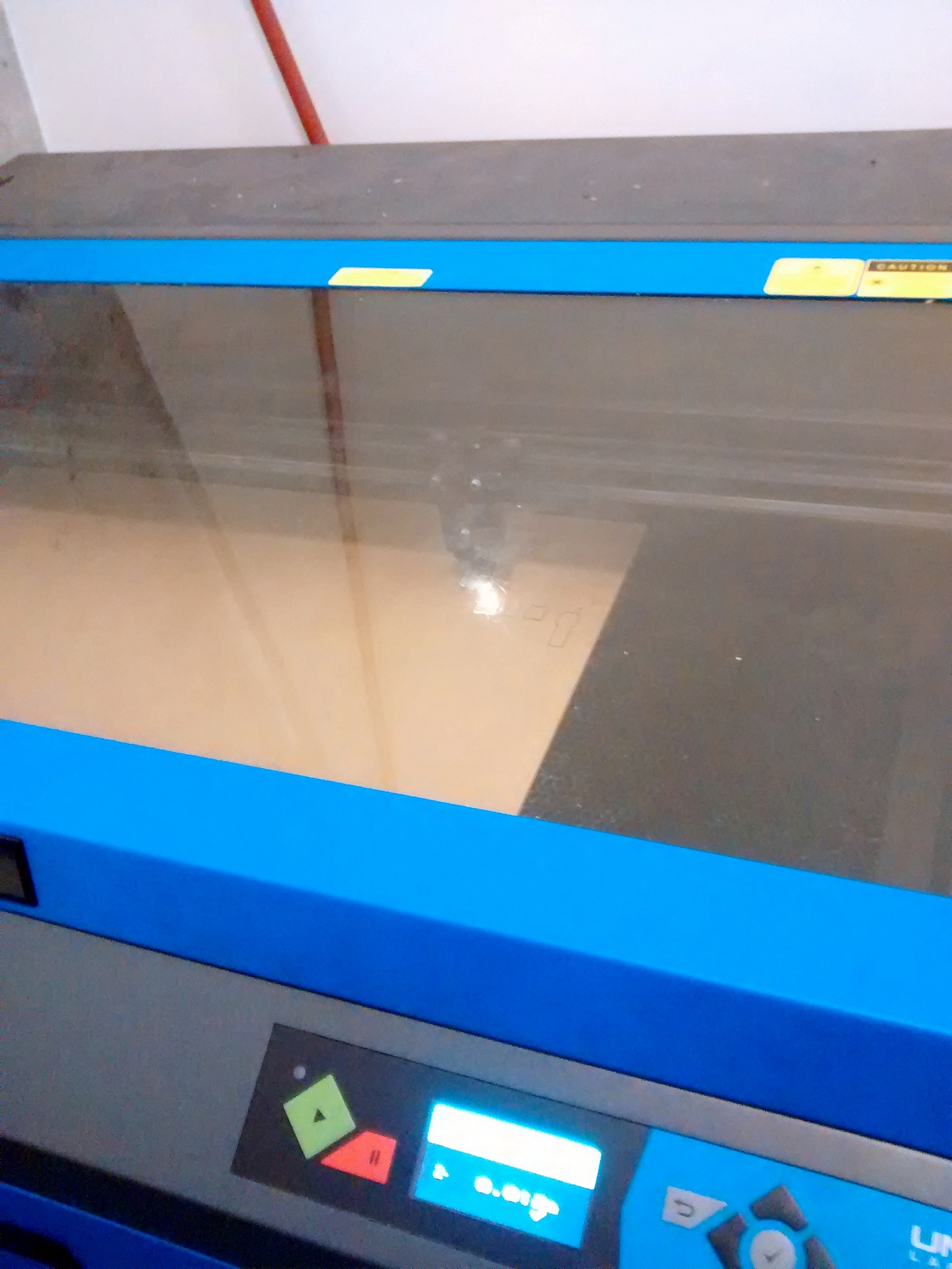
I enlisted Mei to introduce me to the laser cutter and help me cut the sheets. For the most part, it worked out great; there was, however, a pair which suffered some noticeable warping. Fortunately it didn’t impact assembly too much, and we solved that problem by making two laser passes for the remaining sets.
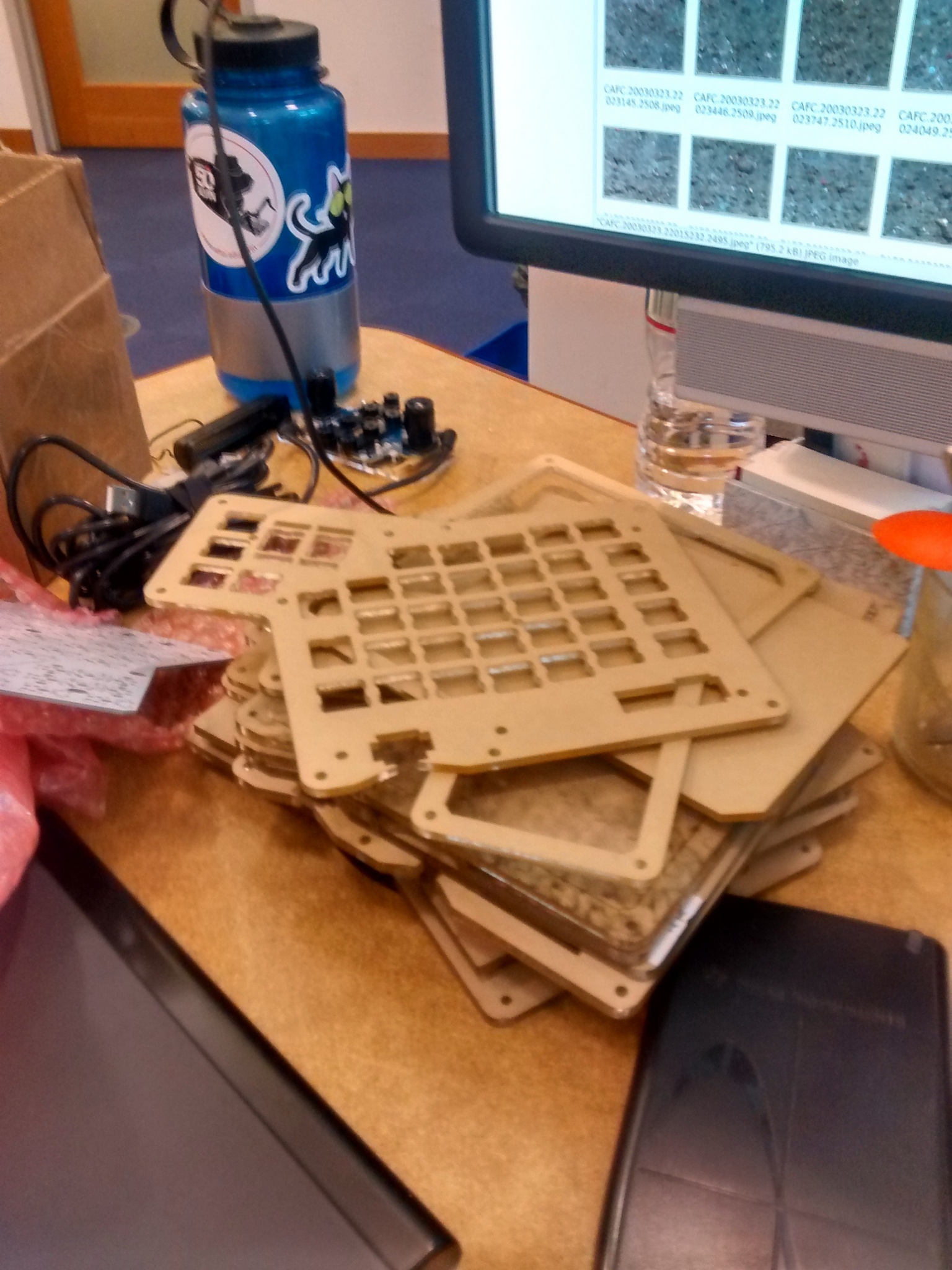
This is the stack of acrylic sheets that form the cases. This is a split keyboard, and each hand requires 5 layers: bottom plate, spacer (for the pcb), stabilizer, another spacer, and the top plate. The original design calls for two 3mm layers and three 4mm layers, but since the layers from McMaster were thicker, I had to use only two of 4.2ish mm - this works out to a thick case, at around 18mm.
PCB
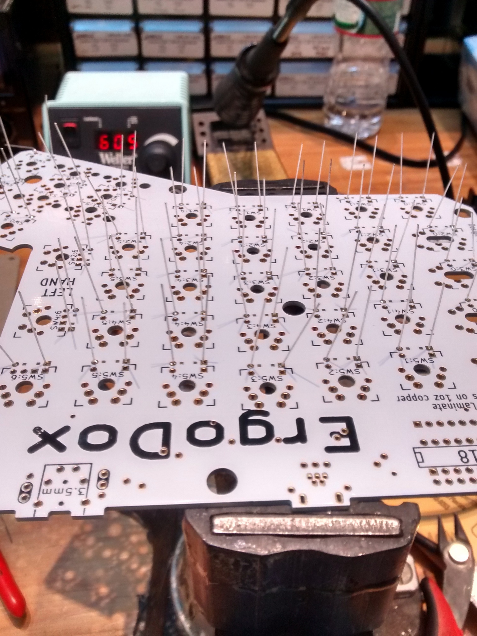
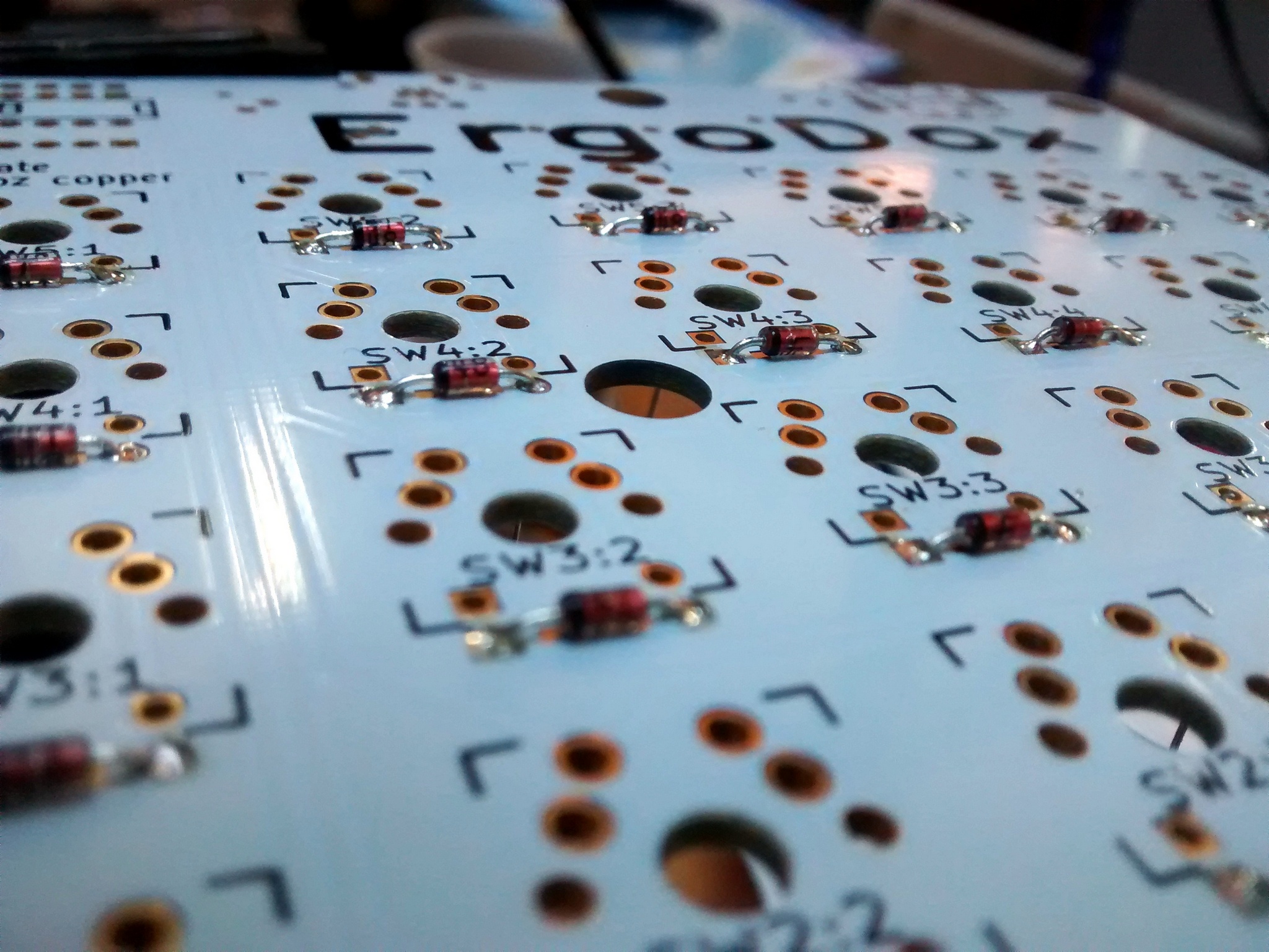
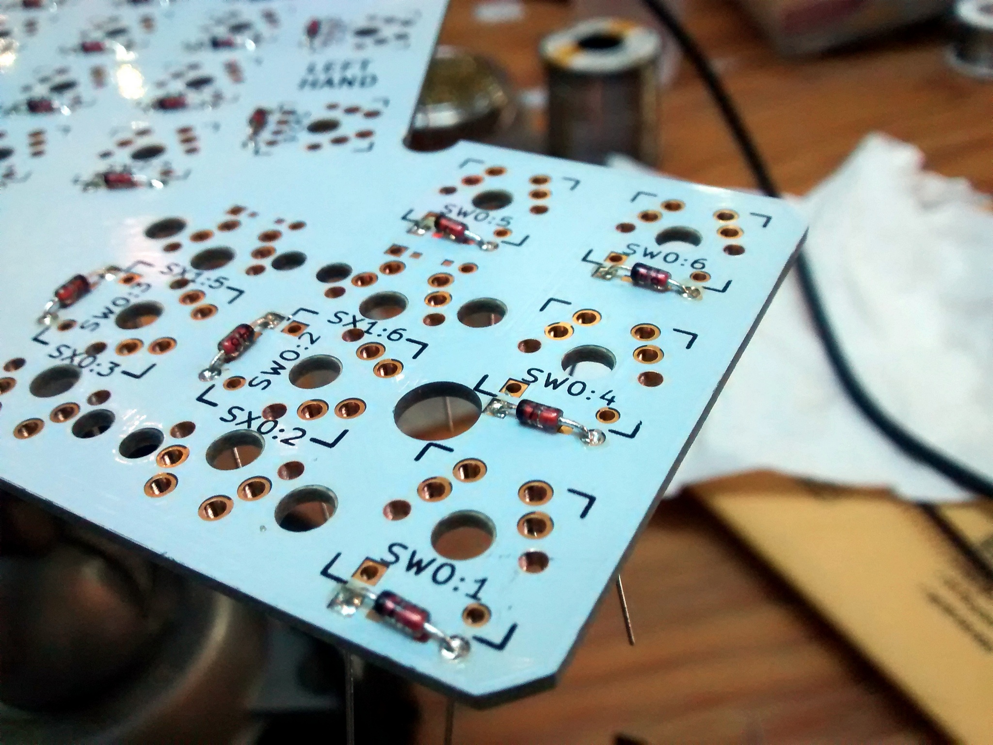
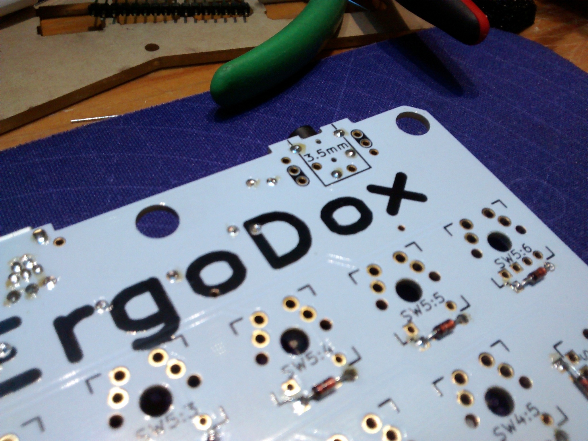
With the case ready, it was time to work on the actual keyboard. Each hand requires 38 keys, each with its own diode - around 400 points for the whole keyboard if you include the other components. Most people use surface-mount diodes, but since I don’t feel too comfortable soldering those, I used regular through-hole 1N4148s. I couldn’t find much information online on using these in the build - probably because it is pretty simple: you just have to solder the diodes on the opposite side of the PCB.
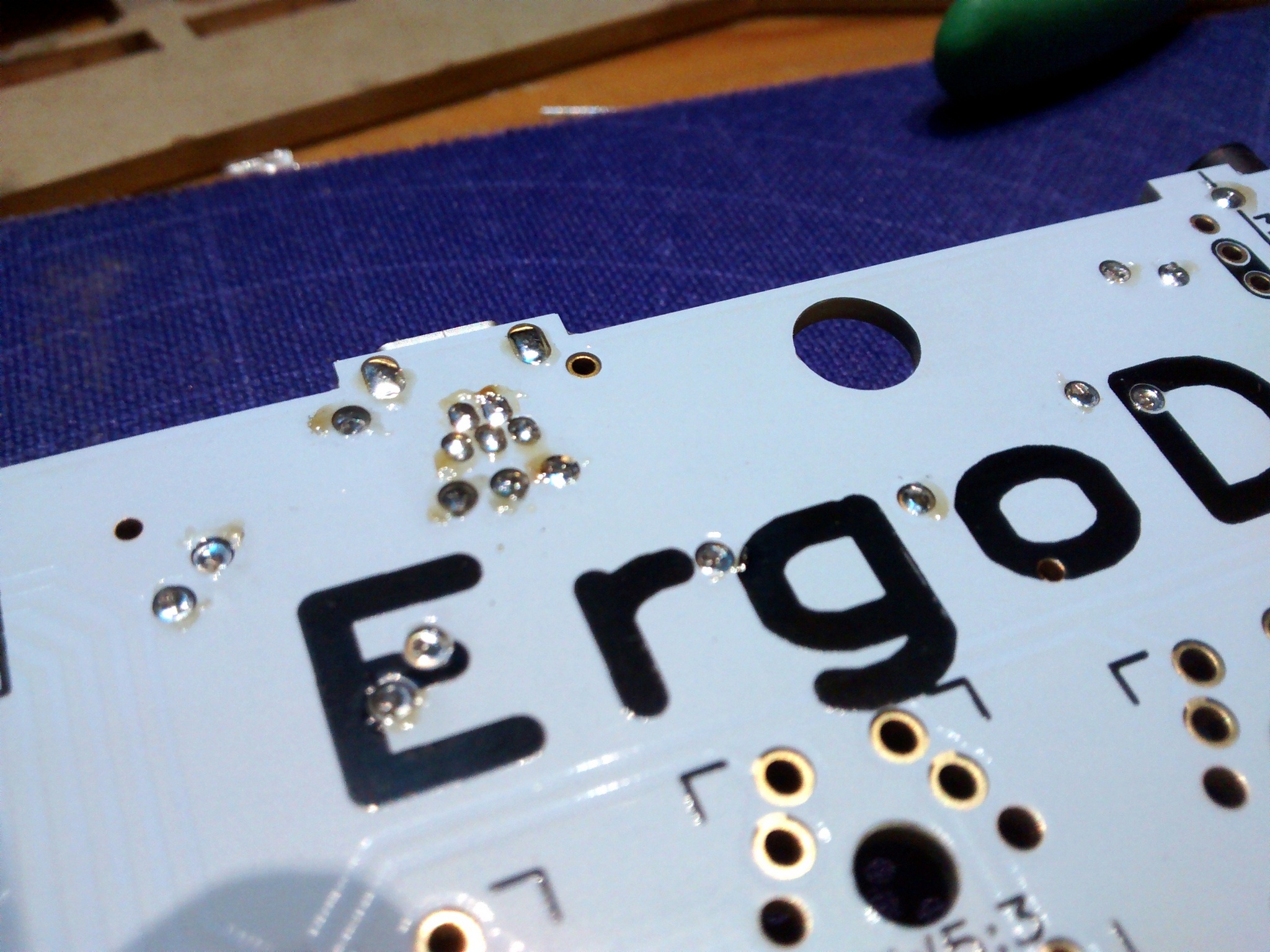
The solder points on the mini USB were awfully close, but didn’t short. The yellow spots are just flux from the solder.
The right hand has a little micro-controller (teensy 2.0) that scans the switches on the right hand, talks to the computer via USB, and to the I/O expander on the left hand via an “audio” cable
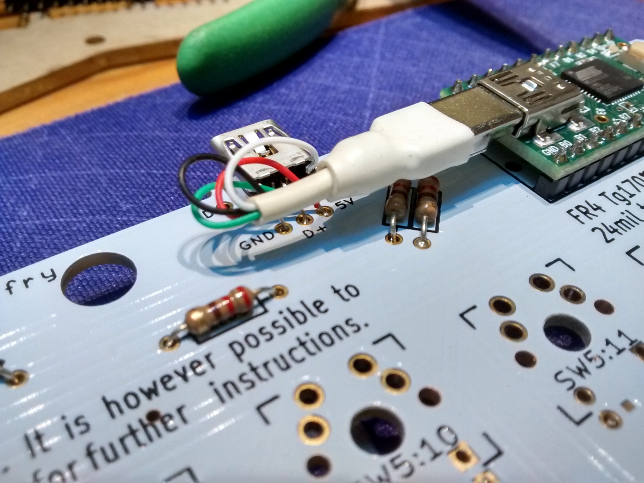
As designed, the connection between the microcontroller and the keyboard’s usb connector is a bit hackish - if I were to do it again, I’d most likely remove the microcontroller’s usb connector and solder the colored wires from there to the white PCB directly.
At this point, all there was left to do was to solder the mechanical switches! One of the acrylic sheets needs to be in place before the switches are soldered (this serves only to stabilize the switches as they’re being pressed) - to prevent smudging/damaging the sheet (and having to de-solder ALL of the switches) I did most of the assembly with gloves (strongly recommended)
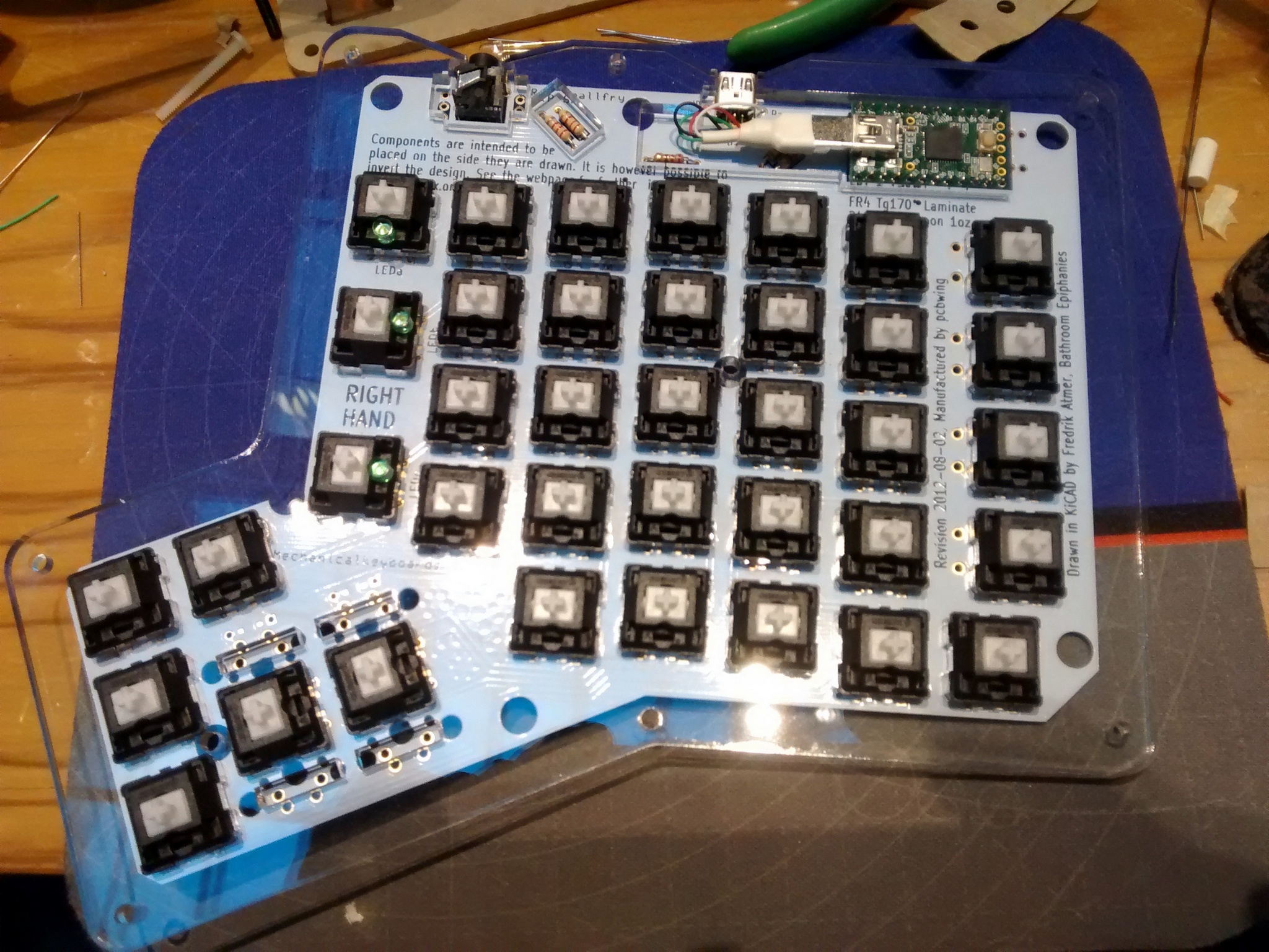
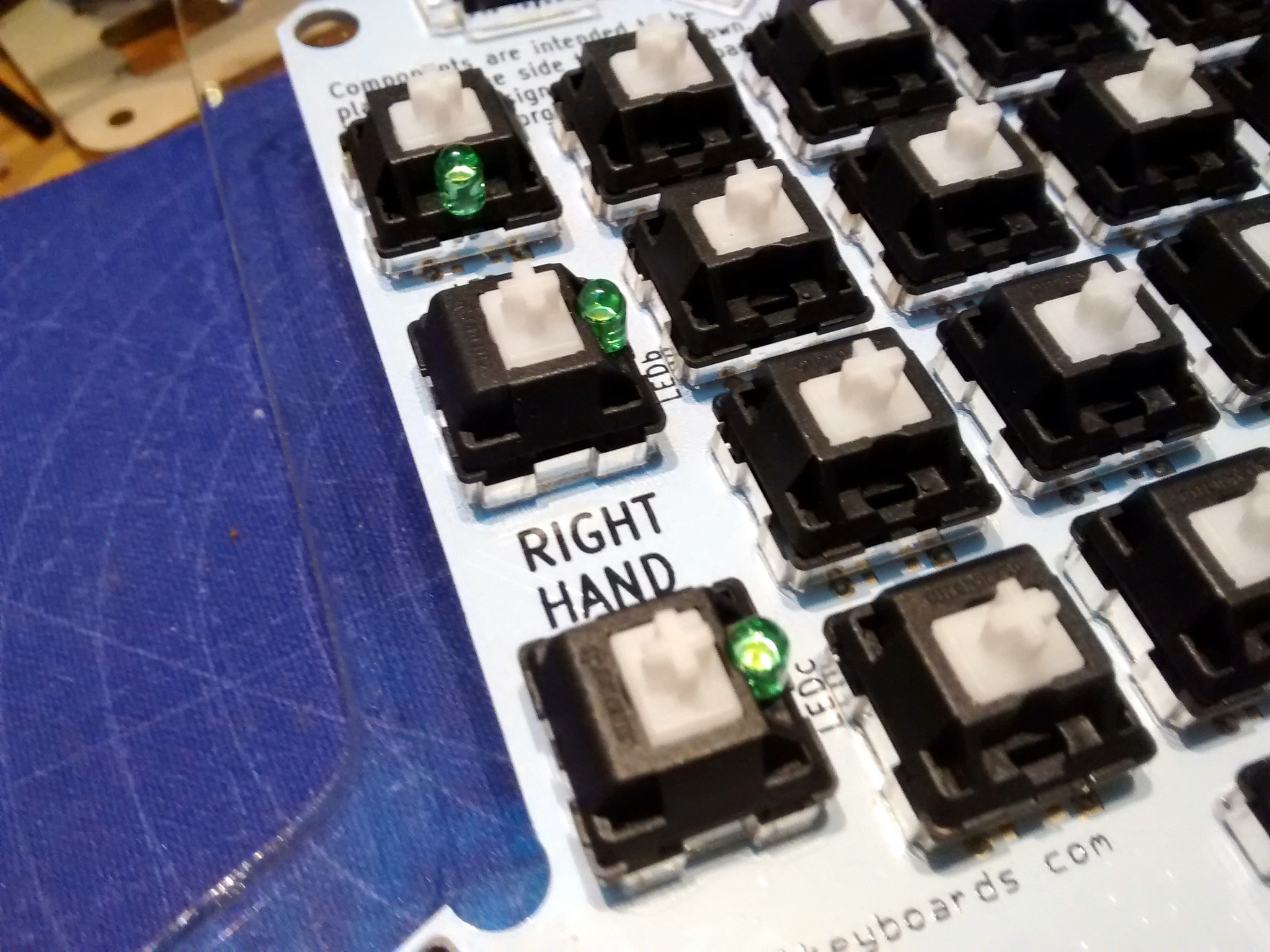
Soldering the LEDs was the trickiest part of all as they have to go through both the switch and the PCB while you can’t even see the leads.
Assembly
Assembly is pretty straightforward, but, as Murphy would have it, it didn’t go according to plan: the diameter of the plastic sleeve on the TRRS connector is slightly larger than the thickness of the spacer layer, keeping the layers from sitting flush with each other.
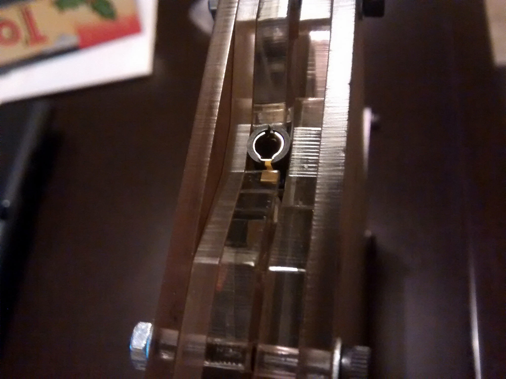
This left me with two options: sand the layers around and/or the connector. I picked up a file and went with the latter; worked great.
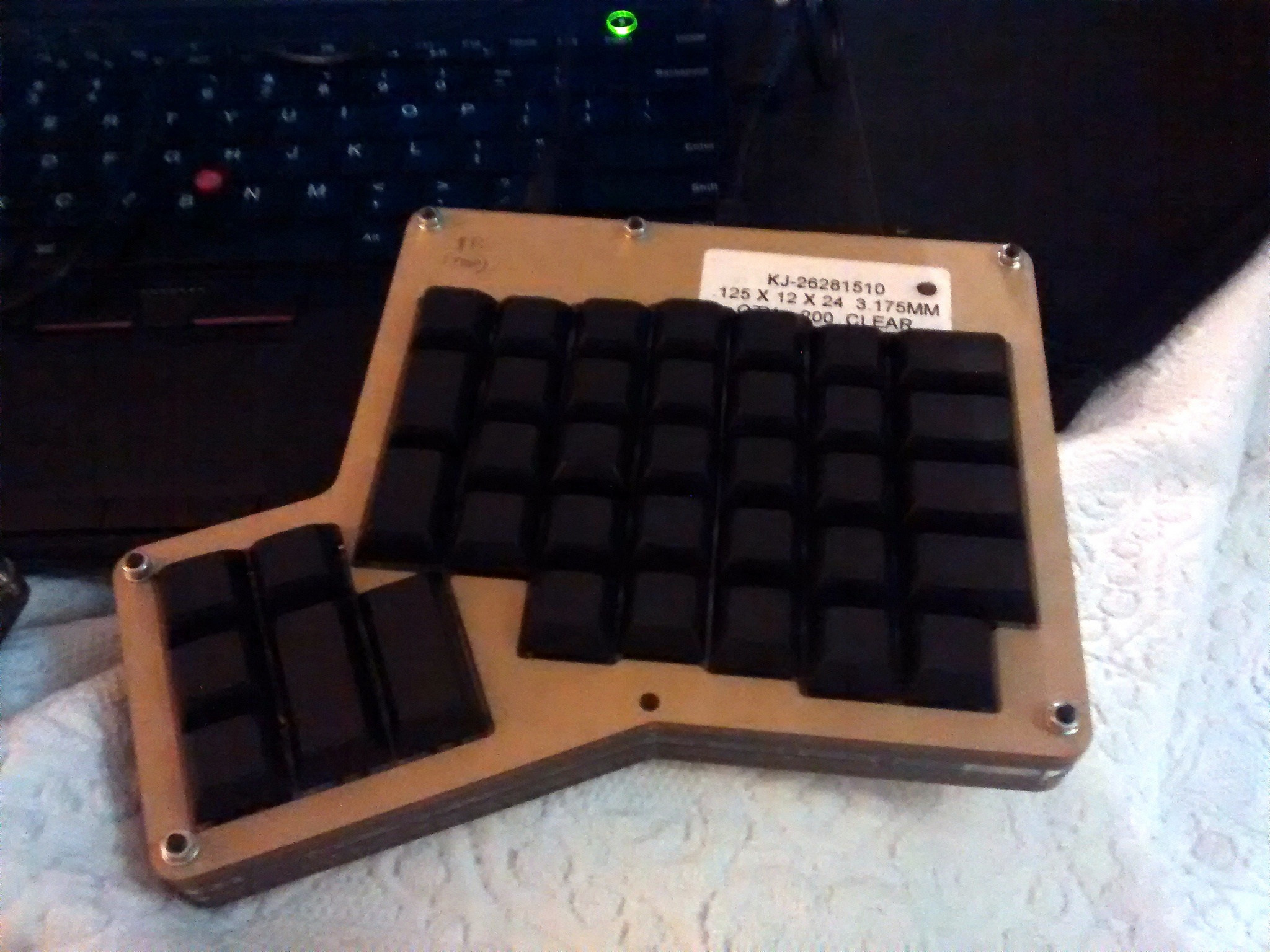
I used a few bolts and nuts to hold the layers together. Since they stick out from both sides, it would be nice to drill the top and bottom plates to use counter-sunk nylon bolts and nuts; As it is currently it may be harsh on the desk.
Conclusion
I found the assembly to be pretty straightforward; the PCBs and acrylic case are well designed and the whole procedure can be done in an afternoon. I managed to complete both hands just in time before my flight to Portugal. As luck would have it, as soon as I give it to my brother he finds that one of the switches hadn’t been soldered - a quick fix and it was finally ready!
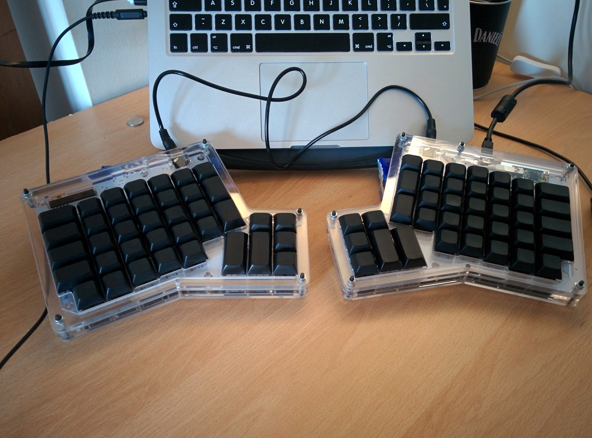
Turns out my keycap choice wasn’t the best - from his feedback I should have gone with labeled keycaps instead. Something like this comes to mind, but I’d still need to find 1.5x keys somewhere…